Specification#
All data is stored following the NCore data specification. If modules use a different convention internally, the conversion should be done within the module, and output data should be converted back to this convention.
Coordinate Systems and Transformations#
There are several coordinate systems that are used in practice - NCore uses the following conventions.
Transformations between Coordinate Systems#
All relative transformations are stored in the form of homogeneous 4x4
\(SE(3)\) matrices, where the top left 3x3 elements represent a rotation
matrix \(\mathbf{R}\) and the first three rows of the last column denote a
translation \(\mathbf{t}\) in the metric units of the sequence. They are
denoted using the identifier T_a_b representing \(T_a^b\), which
corresponds to the transformation matrix that maps the points from the
coordinate system \(a\) to the coordinate system \(b\).
For instance, a point \(\mathbf{p}_a\) in coordinate system \(a\) can be transformed to point \(\mathbf{p}_b\) as
Transformations are chained together by matrix multiplication. For example, given the transformations \(T_a^b\) and \(T_b^c\), the transformation from \(a\) to \(c\) is obtained as
Pose Graph Representation#
NCore represents all spatial relationships in a pose graph – a tree of named coordinate frames connected by rigid transformations. Nodes represent coordinate frames and edges represent \(SE(3)\) transformations between them. The graph forms a tree (no cycles), enabling unambiguous traversal between any pair of frames by composing transformations along the unique connecting path. Edges can be traversed in either direction via \(SE(3)\) inverse.
Edges are either static or dynamic:
Static edges are time-invariant 4x4 \(SE(3)\) matrices. These represent relationships that do not change over time, such as sensor extrinsic calibrations (e.g.,
T_camera_rig), or the mapping between local and global world frames (T_world_world_global).Dynamic edges are time-dependent trajectories – sequences of \(SE(3)\) matrices with associated timestamps. They can be interpolated to arbitrary timestamps using SLERP for the rotation component and linear interpolation for translation. The ego-vehicle trajectory (e.g.,
T_rig_world) is a typical dynamic edge.
A typical pose graph for an AV recording has the following structure:

Example pose graph for a vehicle with an articulated trailer. Dashed edges are static (time-invariant) transforms; bold edges are dynamic (time-dependent) trajectories.#
The well-known coordinate frames are:
rig– the vehicle / robot body frame (see below)world– a sequence-local reference frame (see below)world_global– the earth-centered-earth-fixed (ECEF) global frameSensor frames – named by their sensor ID (e.g.,
camera_front_wide_120fov)
World / Global Coordinate Frame#
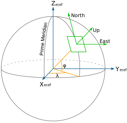
The position and orientation of the ego frame, as well as other objects in the
scene, can be expressed in the earth-centered-earth-fixed (ECEF) world_global
coordinate system in the form of high-precision \(SE(3)\) matrices. To avoid
very large local coordinates and numerical precision issues, NCore uses a local
world coordinate system where one usually stores the first pose of the ego
frame in the sequence to an identity matrix and express all other poses relative
to it. The conversion between the local world and world_global reference
frames is known as T_world_world_global.
Rig Coordinate Frame#
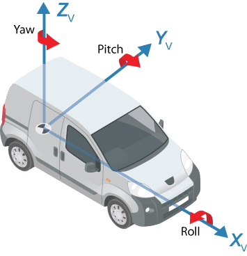
A vehicle / robot-local rig coordinate system is defined as a right-handed
coordinate system with the x-axis pointing to the front of the car, y is
pointing left, and z up. The origin of the coordinate system is located in the
middle of the rear axis on the nominal ground.
A time-dependent trajectory of the ego frame is expressed as T_rig_world.
This can be interpolated to obtain smooth transformations for the start and end
timestamps for each sensor frame (e.g., the start- and end-times of a
rolling-shutter camera frame / spinning lidar frame).
Camera and Image Coordinate System#
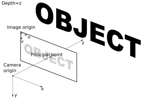
Both extrinsic camera and intrinsic image coordinate systems are right-handed coordinate systems. The axes of the extrinsic camera coordinate system are defined such that the camera’s principal axis is along the +z axis, the x-axis points to the right, and the y-axis points down. The principal point corresponds to the optical center of the camera.
The image coordinate system is defined such that the u-axis points to the right
and the v-axis down. The origin of the image coordinate system is in the top
left corner of the image, and the units are pixels. Continuous pixel coordinates
start with [0.0, 0.0] at the top-left corner of the top-left pixel in the
image, i.e., both the u and v coordinates of the first pixel span the range
[0.0, 1.0].
Sensor Models#
NCore supports multiple sensor models for camera and lidar intrinsics and distortion parameters. For the full list of supported models, mathematical specifications, and parameter descriptions, see Sensor Models.