NCore Data Sanity Check#
This tutorial provides guidance for data sanity check.
For more information on the data loader and APIs, please refer to data_loading.
Please use your own data for sanity checks.
We can follow the [Check List] indicators in the text to systematically review the data.
[ ]:
# We start with loading a list of V4 component groups using the NCORE's component grouo loader and the sequence loader APIs

component_group_path = Path("<PATH>/ncore-demo/sequence-ncore4.json")  # adapt to local V4 sequence meta file

# V4 API provides direct access to component data
from ncore.data.v4 import SequenceComponentGroupsReader, SequenceLoaderV4

# Load low-level component groups
group_reader = SequenceComponentGroupsReader([component_group_path])

# Use sequence loader to load data with convenient APIs
loader = SequenceLoaderV4(group_reader)
[3]:
# Next we inspect some of the general properties of the dataset with methods exposed by the loader.

# Sequence information
print(f'sequence-id: {loader.sequence_id}')

# List all sensor IDs of different sensor types in loaded data
print(f'lidar sensors: {loader.lidar_ids}')
print(f'camera sensors: {loader.camera_ids}')
sequence-id: c12961c2-4329-11ec-bcb5-00044bcbccac
lidar sensors: ['lidar_gt_top_p128_v4p5']
camera sensors: ['camera_right_fisheye_200fov', 'camera_rear_right_70fov', 'camera_rear_tele_30fov', 'camera_rear_left_70fov', 'camera_rear_fisheye_200fov', 'camera_front_wide_120fov', 'camera_cross_right_120fov', 'camera_front_fisheye_200fov', 'camera_left_fisheye_200fov', 'camera_cross_left_120fov']
Section1: Poses#
We inspect some pose / trajectory properties of the sequence by inspecting the sequence-associated pose-graph:
[4]:
global_pose = unpack_optional(loader.pose_graph.get_edge("world", "world_global")) # *full* pose / rig trajectory data
rig_poses = unpack_optional(loader.pose_graph.get_edge("rig", "world")) # *full* pose / rig trajectory data

print('ECEF-aligned base pose (SE3):\n', global_pose.T_source_target, '\n')
ECEF-aligned base pose (SE3):
 [[      -0.7085495276572739        -0.5165307835309174        -0.48078426441685684 -2672408.693024274        ]
 [       0.7030619419398989        -0.45831159857852444       -0.5437410887037756  -4271966.408560775        ]
 [       0.06051000624771203       -0.723288651254294          0.6878895716550725   3897142.112033472        ]
 [       0.                         0.                         0.                         1.                 ]]
[5]:
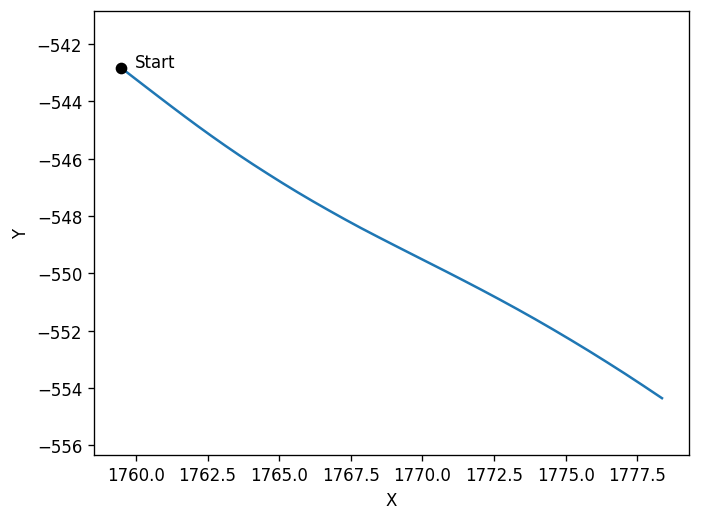
# We can visualize the rig-to-world trajectory by rendering a BEV(bird-eye-view) of the 2d x/y positions.

# Please pay attention to the x/y directions.

plt.plot(
    # x coordinates in 4x4 pose
    rig_poses.T_source_target[:, 0, 3:],
    # y coordinates in 4x4 poses
    rig_poses.T_source_target[:, 1, 3:],)

plt.scatter(rig_poses.T_source_target[0, 0, 3:], rig_poses.T_source_target[0, 1, 3:], color='black', zorder=5, label='Marker')
plt.text(rig_poses.T_source_target[0, 0, 3:].item() + 0.5, rig_poses.T_source_target[0, 1, 3:].item(), 'Start', fontsize=10, color='black')

plt.axis('equal')
plt.xlabel('X')
plt.ylabel('Y')
plt.show()
[6]:
# We can also visualize the rig-frames coordinate axis by projecting them onto the cameras

front_cam_id = "camera_front_wide_120fov"
show_rig_direction(front_cam_id, loader, origin_offset = np.array((5, 0, 0)))

side_cam_id = "camera_cross_left_120fov"
show_rig_direction(side_cam_id, loader, origin_offset = np.array((2, 5, 0)))

rear_cam_id = "camera_rear_tele_30fov"
show_rig_direction(rear_cam_id, loader, origin_offset = np.array((-15, 0, 0)))

# From the projection result, we can see the rig axis directions relative to the world: X - front; Y - left; Z: up
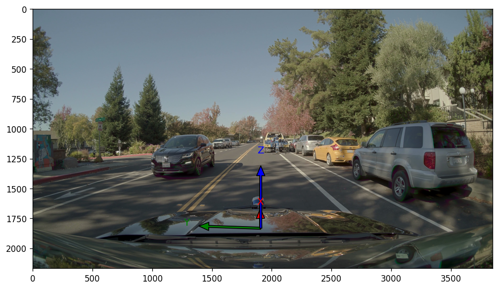
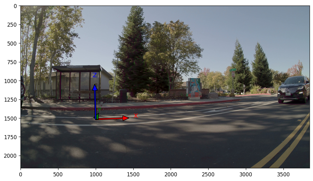
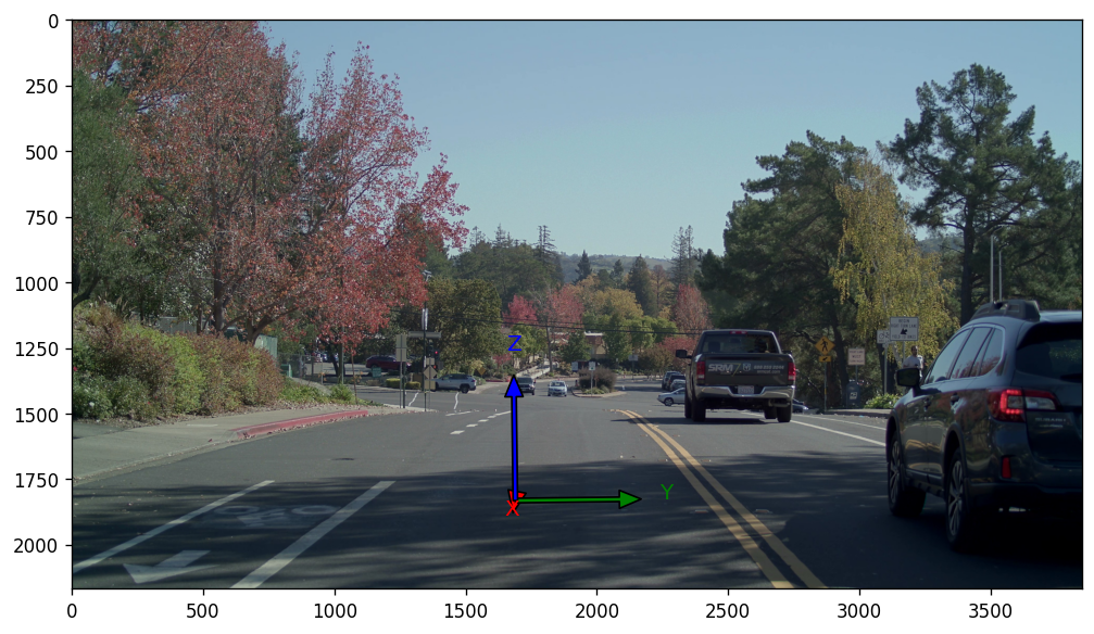
[Check List]
The results should match the illustrations in the documentation.
Section2: LiDAR#
[7]:
# First, some overview sanity-check
lidar_sensors = [loader.get_lidar_sensor(lidar_id) for lidar_id in loader.lidar_ids]

for lidar_sensor in lidar_sensors:
    lidar_id = lidar_sensor.sensor_id
    print(f"Checking {lidar_id}.")

    # Sensor's extrinsics
    print('lidar extrinsics:\n', unpack_optional(lidar_sensor.T_sensor_rig), '\n')
    # Available frame ranges
    print('lidar frame range:\n', lidar_sensor.get_frame_index_range(), '\n')

    # check intensity
    for lidar_frame_idx in lidar_sensor.get_frame_index_range():
        intensity = lidar_sensor.get_frame_ray_bundle_return_intensity(lidar_frame_idx)
        assert (intensity >= 0).all and (intensity <= 1).all, "Intensity should be between 0 and 1."

    # check timestamp
    for lidar_frame_idx in lidar_sensor.get_frame_index_range():
        timestamp_us = lidar_sensor.get_frame_ray_bundle_timestamp_us(lidar_frame_idx)
        timestamps_startend_us = [
                    lidar_sensor.get_frame_timestamp_us(
                        lidar_frame_idx, frame_timepoint=FrameTimepoint.START
                    ),
                    lidar_sensor.get_frame_timestamp_us(lidar_frame_idx, frame_timepoint=FrameTimepoint.END),
                ]

        # For motion compensation, we need the point's timestamps restricted within the frame's start/end times.
        assert (
            (timestamps_startend_us[0] <= timestamp_us).all()
            and (timestamp_us <= timestamps_startend_us[1]).all()
        ), f"{lidar_id}: Lidar point timestamps out of frame timestamp bounds"
Checking lidar_gt_top_p128_v4p5.
lidar extrinsics:
 [[ 0.9999579     -0.00916378     0.00041632314  1.1885       ]
 [ 0.009162849    0.99995565     0.0021855677   0.           ]
 [-0.00043633272 -0.002181661    0.9999975      1.86655      ]
 [ 0.             0.             0.             1.           ]]

lidar frame range:
 range(0, 34)
We perform multi-frame point cloud fusion to validate poses and LiDAR calibrations.
If the multi-frame point clouds of static objects align, then the calibration and poses can be considered to be accurate.
If the point clouds don’t align but the projection check (see camera section) is valid then this indicates tha the poses are incorrect.
[8]:
# Initialize a canvas. We are going to draw point clouds(in world coordinates) from a BEV view.
# Set a ROI based on the pose range and LIDAR scan distance, along with the corresponding visualization scale ratio.
lidar_range = 50    # range of the point cloud
ratio = 20          # ratio of the visualization scale
xmin = np.floor(rig_poses.T_source_target[:, 0, 3].min() - lidar_range).astype(np.int16)
xmax = np.ceil(rig_poses.T_source_target[:, 0, 3].max() + lidar_range).astype(np.int16)
ymin = np.floor(rig_poses.T_source_target[:, 1, 3].min() - lidar_range).astype(np.int16)
ymax = np.ceil(rig_poses.T_source_target[:, 1, 3].max() + lidar_range).astype(np.int16)
ROI = np.array([[xmin, ymin],[xmax, ymax]])

width = (ROI[1, 0 ]- ROI[0, 0]) * ratio
height = (ROI[1, 1] - ROI[0, 1]) * ratio
img = np.zeros([height, width, 3], dtype=np.uint8)
cmap = plt.get_cmap("rainbow")
plt.figure(figsize=[10, 10])

for lidar_idx, lidar_sensor in enumerate(lidar_sensors):
    n_frames = min(len(lidar_sensor.get_frame_index_range()), 100)
    for frame_idx in tqdm(range(0, n_frames, 5)):
        # Motion-compensated points in end-of-spin frame
        points = lidar_sensor.get_frame_point_cloud(frame_idx, motion_compensation=True, with_start_points=False).xyz_m_end
        points = ncore_transformations.transform_point_cloud(
            points, lidar_sensor.get_frames_T_sensor_target("world", frame_idx)
        )  # transform lidar to world

        points = points[np.logical_and(points[:, 0] > ROI[0, 0], points[:, 0] < ROI[1, 0])]
        points = points[np.logical_and(points[:, 1] > ROI[0, 1], points[:, 1] < ROI[1, 1])]

        v = np.floor((points[:, 0] - ROI[0, 0]) * ratio).astype(np.int16)            # x
        u = np.floor(height - (points[:, 1] - ROI[0, 1]) * ratio).astype(np.int16)   # y

        color = (np.array(cmap((lidar_idx * n_frames + frame_idx) / n_frames))[:3] * 255).astype(np.uint8)
        img[u, v, :] = color

plot_image(img)
100%|██████████| 7/7 [00:00<00:00, 9.69it/s]
[Check List]
The static objects should align.
The point cloud trajectory observed from the fusion results should align with what is seen in the video.
For example, if the video shows the ego-vehicle making a left turn, but the fused point cloud suggests a right turn, then there is a discrepancy.
[9]:
# We can also export the point clouds and check with an external viewer

%pip install point-cloud-utils --quiet
from point_cloud_utils import TriangleMesh

output_dir = "/tmp/ncore-demo/output"
os.makedirs(output_dir, exist_ok=True)
n_frames = min(len(lidar_sensor.get_frame_index_range()), 10)
cmap = plt.get_cmap("rainbow")

for lidar_idx, lidar_sensor in enumerate(lidar_sensors):
    for frame_idx in tqdm(range(n_frames)):
        points = lidar_sensor.get_frame_point_cloud(frame_idx, motion_compensation=True, with_start_points=False).xyz_m_end
        intensity = lidar_sensor.get_frame_ray_bundle_return_intensity(frame_idx)

        points = ncore_transformations.transform_point_cloud(
            points, lidar_sensor.get_frames_T_sensor_target("world", frame_idx)
        )  # transform from lidar to world
        colors = (cmap(intensity)[:, :3] * 255).astype(np.uint8)

        tm = TriangleMesh()
        tm.vertex_data.positions = points
        tm.vertex_data.colors = colors
        tm.save((f"{output_dir}/{lidar_idx}_{frame_idx}.ply"))
Note: you may need to restart the kernel to use updated packages.
100%|██████████| 10/10 [00:01<00:00, 7.57it/s]
[Check List]
Check motion compensation:
In NCore, the point cloud is supposed to be motion-compensated.
Select data where the ego-vehicle is in motion.
Zoom in to inspect the motion compensation of slender objects (e.g., tree trunks, streetlights) and other vehicles.
Check for thickness in the ground after multi-frame fusion.
The greater the thickness, the larger the pose error.
Section3: Camera#
We perform point-to-camera projections to verify calibrations and time-alignment.
The point clouds should project perfectly onto the images, overlaying with the 3d geometry observed in the image frame.
[Check List]
Select a frame when the ego-car is static
If the projection fails then the camera model parameters or relative cam-lidar extrinsics calibration can be considered erroneous;
Inaccurate point cloud projections on dynamic objects are tolerable. Please pay more attentaion on static objects.
Select a frame when the ego-car is moving
If the projection fails and the multi-frame point-cloud fusion was successful (see last section), then it indicates there is an issue related to timestamp consistency of camera rolling shutter parameter.
[10]:
image_frames = []
image_point_projections = []

# point cloud frame at center of stream
lidar_frame_idx = lidar_sensor.frames_count // 2 + 2
lidar_frame_timestamp_us = lidar_sensor.get_frame_timestamp_us(lidar_frame_idx, FrameTimepoint.END) # get timestamp of lidar frame (end-of-frame)
point_cloud_sensor = lidar_sensor.get_frame_point_cloud(lidar_frame_idx, motion_compensation=True, with_start_points=False).xyz_m_end
point_cloud_world = ncore_transformations.transform_point_cloud(point_cloud_sensor, lidar_sensor.get_frames_T_sensor_target("world", lidar_frame_idx))

for camera_sensor in tqdm(camera_sensors := [loader.get_camera_sensor(camera_id) for camera_id in loader.camera_ids]):

    # Initialize camera intrinsics
    camera_model_params = camera_sensor.model_parameters
    camera_model = CameraModel.from_parameters(camera_model_params, device='cpu')  # we use 'cpu' for increased compatibility / can also run on 'cuda' device

    # Determine closest camera frame relative to lidar-frame
    camera_frame_idx = camera_sensor.get_closest_frame_index(lidar_frame_timestamp_us)

    # Load the camera image
    image_frames.append(camera_sensor.get_frame_image_array(camera_frame_idx))

    # Obtain poses for rolling-shutter projection
    T_world_sensor_start, T_world_sensor_end = camera_sensor.get_frames_T_source_sensor("world",
                                                                                        camera_frame_idx,
                                                                                        None)

    # Project point cloud into camera frame using rolling-shutter motion-compensation
    image_point_projections.append(camera_model.world_points_to_image_points_shutter_pose(point_cloud_world,
                                                                                          T_world_sensor_start,
                                                                                          T_world_sensor_end,
                                                                                          return_T_world_sensors=True,
                                                                                          return_valid_indices=True))

plt.figure(figsize=(30, len(camera_sensors) * 12))

for i, (image_frame, image_point_projection) in tqdm(enumerate(zip(image_frames, image_point_projections))):
    plt.subplot(len(camera_sensors), 1, i+1)
    plot_points_on_image(point_cloud_world, image_point_projection, image_frame)

plt.show()
100%|██████████| 10/10 [00:01<00:00,  9.63it/s]
10it [02:48, 16.83s/it]
[11]:
# Visualize the ego masks
camera_sensors = [loader.get_camera_sensor(camera_id) for camera_id in loader.camera_ids]
plt.figure(figsize=(10, len(camera_sensors) * 4))

observe_frame_idx = 0    # egomask is consistent across frames
for i, camera_sensor in tqdm(enumerate(camera_sensors)):
    plt.subplot(len(camera_sensors), 1, i+1)
    camera_image = camera_sensor.get_frame_image_array(observe_frame_idx)

    if camera_mask_image := camera_sensor.get_mask_images().get("ego"):
        # True for parts that we want to mask out
        mask = (np.asarray(camera_mask_image.convert("L"))!= 0)

        out = np.minimum(255, np.maximum(0, (camera_image * 0.5 + mask[:,:, np.newaxis] * 255 * 0.5))).astype(np.uint8)
        plot_image(out)
    else:
        print(f"No ego-mask for {camera_sensor.sensor_id}")
10it [00:11, 1.14s/it]
[Check List]
Check whether each camera has an ego mask and check their accuracy.
[12]:
## Verify that the labels are in the correct coordinates by projecting them onto the images.

# observe frames at center of stream
lidar_sensor = loader.get_lidar_sensor(loader.lidar_ids[0])
observe_lidar_frame_idx = lidar_sensor.frames_count // 2

# observe selected cameras
draw_boxes_on_image(loader, camera_ids=loader.camera_ids, lidar_sensor=lidar_sensor, lidar_frame_idx=observe_lidar_frame_idx)
[Check List]
The 3D boxes should correspond one-to-one with the targets.
Here, we are only checking the correctness of the coordinate system. If the boxes are inaccurate, please refine your source data.
Boxes that are occluded are displayed.
All the boxes with their
track_iddisplayed on top.
We also suggest checking the alignment between boxes and point clouds using
//scripts:ncore_visualize_labels.
[13]:
# check timestamp
for camera_sensor in tqdm(camera_sensors):
    for camera_frame_idx in camera_sensor.get_frame_index_range():
        timestamp_start = camera_sensor.get_frame_timestamp_us(
                        camera_frame_idx, frame_timepoint=FrameTimepoint.START
                    )
        timestamp_end = camera_sensor.get_frame_timestamp_us(
                        camera_frame_idx, frame_timepoint=FrameTimepoint.END
                    )

        assert (
            timestamp_start <  timestamp_end
        ), f"{camera_sensor.sensor_id}: End timestamp must be larger than the start timestamp."
100%|██████████| 10/10 [00:00<00:00, 20733.09it/s]