

lidar_point_cloud (FET036 RTX Sensors)#
Property |
Value |
|---|---|
Test name |
lidar_point_cloud |
Feature(s) |
FET_036_RTX |
Engine |
Kit / Isaac Sim (>=2024.2.0) |
Test version |
0.1.0 |
Running with simready-benchmark#
This test is implemented and available in the simready-benchmark-kit-suite package.
Run it against an asset:
simready-benchmark --assets path/to/asset.usd --features FET036
The test skips automatically if no OmniLidar prim with OmniSensorGenericLidarCoreAPI is found, or if all LiDAR buffers are empty after the scan (environment limitation — GPU driver >= 576.x required for RTX LiDAR CUDA 12.9 support in Isaac Sim 6.0.1).
Summary#
Loads the asset into a physics scene containing a simple ground plane and a reference object, steps the simulation for one full LiDAR scan cycle, and confirms that each OmniLidar prim produces a non-empty point cloud.
What Pass Guarantees#
A reviewer, PM, or OEM can trust that the OmniLidar prim is correctly typed
and configured (using OmniSensorGenericLidarCoreAPI as required by LI.001)
so that Isaac Sim can initialize the sensor and produce range data. The asset
is ready for use in mapping, obstacle avoidance, or synthetic data generation
pipelines that depend on LiDAR output.
What It Checks#
After stepping the simulation for scan_frames (default 120) frames:
Point count: the
GenericModelOutputbuffer must be non-empty (at least one point). An empty buffer afterscan_framesis treated as an environment limitation and the test is skipped, not failed.Finite values: all values in the buffer must be finite (no NaN or Inf).
The test does NOT check range values or min_range_m. If the asset has multiple OmniLidar prims, all are checked independently.
Key thresholds from config_defaults:
scan_frames: 120 (frames run — RTX rendering needs more warmup than physics sensors)
How It Works#
The test uses prim.GetMetadata("apiSchemas").GetAppliedItems() alongside prim.GetTypeName() == "OmniLidar" to find all conforming LiDAR prims. If none are found, the test is skipped.
A ground plane and a reference cube above ground are added via omni.kit.commands.execute("CreateMeshPrimWithDefaultXform", ...) so the LiDAR emitters have varied geometry at multiple heights to scan.
LidarRtx sensors are initialised with attach_annotator("GenericModelOutput") and initialize() before simulation starts — the RTX pipeline requires early attachment.
Physics is driven using direct API calls (omni.physx.get_physx_interface().start_simulation() + omni.timeline.get_timeline_interface().play() + raw next_update_async() calls) rather than the framework’s ctx.physics_step(). This is necessary because ctx.physics_step() pauses the timeline after the first frame to prevent multi-frame auto-advancement, which stops RTX sensor scan updates. RTX LiDAR sensors require the timeline to remain continuously playing to fire their scan callbacks.
After scan_frames frames, lidar.get_current_frame() is read from each sensor. If all buffers are empty (GPU driver limitation), the test is skipped. If any buffer contains data, the non-empty and all-finite conditions are checked.
Failure Cases#
Symptom |
Likely cause |
|---|---|
Point cloud is empty (zero points) |
The sensor emitters are all directed away from the test geometry, the |
NaN or Inf in point coordinates |
An emitter state array has a length mismatch with |
Range values at exactly zero |
The sensor is returning null returns. Check that |
All range values equal |
All emitters are directed at empty space. The sensor is functioning but the emitters are not aimed at the test objects. This is not a sensor error but may indicate an incorrect sensor orientation in the asset. |
Test skipped (not applicable) |
No |
How to Fix#
If the point cloud is empty, verify that the sensor’s emitter elevation and
azimuth angles (in omni:sensor:Core:emitterState:*:elevationDeg and
azimuthDeg) include directions that intersect the ground plane or nearby
objects. Check that nearRangeM is less than 1.0 m (the distance to the test
ground plane).
If array lengths are mismatched, ensure every
omni:sensor:Core:emitterState:* attribute array has exactly
numberOfEmitters elements (LI.002).
Manual Testing in Isaac Sim#
Batch script#
The canonical batch script lives at batch_test_lidar_point_cloud.py in the
repo root. Run it with:
# Windows
isaac-sim.bat --no-window --exec "C:\Dev\simready_foundations\batch_test_lidar_point_cloud.py"
# Linux
./isaac-sim.sh --no-window --exec "/path/to/simready_foundations/batch_test_lidar_point_cloud.py"
Expected output summary:
Overall: PASS (2/2 checks passed)
Note: The script tests both rotary and solid-state LiDAR sensors. Both sensor types use
Lidar(prim_path)to wrap the existing prim, provided the USDA file declaresmetersPerUnit = 1in its layer header. Without this, USD falls back to 0.01 m/unit, placing the test geometry out of sensor range and producing zero returns. Seebatch_test_lidar_point_cloud.pyfor the full implementation.
Expected Result#
The test saves an azimuth-vs-elevation scatter plot PNG to the run output directory for each OmniLidar prim. The horizontal axis is azimuth (left = leftmost beam, right = rightmost beam) and the vertical axis is elevation (top = highest beam, bottom = lowest beam). Each dot is one LiDAR return, colored by range (blue = near, red = far). The visual appearance depends on the sensor type:
Solid-state sensor (OmniLidarSolidStateRTXPass.usda)#
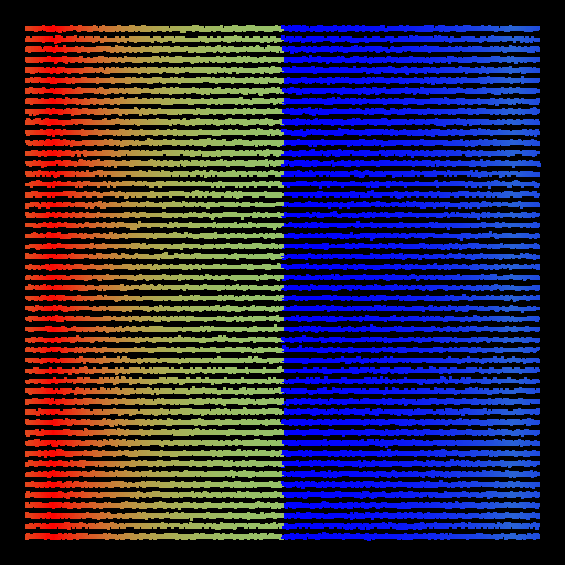
A solid-state lidar fires a fixed rectangular grid of emitters. The result is a fully-filled 2D rectangle — the sensor’s complete scan pattern with no gaps. The color gradient reflects varying distances to the sarcophagus walls placed around the sensor during the test.
Rotary sensor (OmniLidarCheckerPass.usda)#
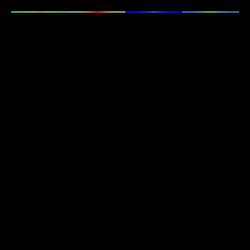
A rotary lidar sweeps 360° in azimuth at one or a small number of fixed elevation angles. The result is one or more horizontal bands spanning the full width of the image — one band per emitter elevation row. The color gradient reflects varying distances to the sarcophagus walls at different azimuths.